D900-06-00 1 I56-750-58
SS24ADAS Series Strobes and
MASS24ADAS Series Synchronized
Horn/Strobes for Fire Protective
Signaling Systems
INSTALLATION AND MAINTENANCE INSTRUCTIONS
A Division of Pittway
3825 Ohio Avenue, St. Charles, Illinois 60174
1-800-SENSOR2, FAX: 630-377-6495
General Description
The National Fire Protection Association has published
standards and recommended practices for the installation
and use of the listed appliances. It is recommended that the
installer be familiar with these requirements, with local
codes, and any special requirements of the local fire au-
thority having jurisdiction.
The Multi-Alert™ sounder and signaling strobe are intended
to be connected to the alarm indicating circuit of a UL-
listed fire alarm control panel and is compatible with DC
line supervision. The electronic sounder can be connected
to either 12 or 24 VDC panels. Models SS2415ADAS,
SS241575ADAS, and combination models incorporating
these strobes, require 24 volt panels. Panels may have full-
wave rectified, unfiltered power supplies. The strobes are
synchronized and flash at a rate of one flash per second
with continuous voltage applied. SS24ADAS, SS24ADA,
MASS24ADAS, and MASS24ADA series devices may be
combined in the same zone.
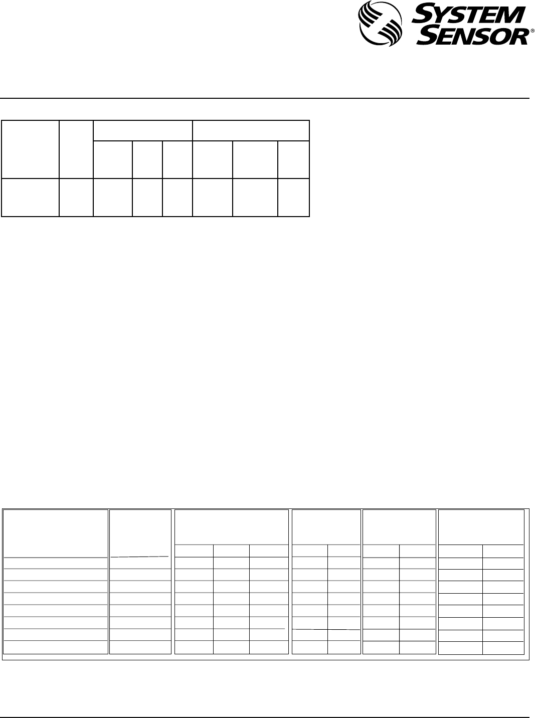
Model Supply Operating Current from Operating Current from Full-Wave
Voltage Regulated Supply Rectified Unfiltered Supply
Range
SS2415ADAS 20-30V 106 200 5.0/7.0 125 250 5.0/7.0
SS241575ADAS 20-30V 195 350 5.0/7.0 180 395 5.0/7.0
Average Peak Inrush Average Peak Inrush
Operating Current Current Operating Current Current
Current (mA) (Amps) Current (mA) (Amps)
(mA) 20/30 (mArms) 20/30
Vrms Vrms
NOTE: In-rush current duration is less than 20
microseconds (.00002 seconds).
Table 2. Sound output and current ratings for the MA12/24D:
Sound (Hz) Clips on Current (mA) Output (dBA)
UL (dBA)
UL (dBA)
Tabs DC Regulated/ (Note 3)
Ratings
w/MDL Module
(Note 1) FWR Unfiltered (Note 4) Temp. Tone (Note 5)
12V 24V 30V 12V 24V 12V 24V 12V 24V
Slow Whoop ABC 21/40 38/56 46/72 85 92 79 85 N/A N/A
800 Continuous BC 15/24 28/45 35/55 87 93 79 85 75 79
800/1000 Alternating AC 17/32 34/46 43/58 85 92 79 85 N/A N/A
2400 Interrupted AB 19/23 35/56 43/64 89 90 79 85 N/A N/A
2400 Continuous C 21/31 38/59 46/73 85 94 79 85 75 79
1200 Interrupted B 13/19 23/33 27/41 85 91 75 82 N/A N/A
Swept Frequency A 17/24 34/47 43/60 85 92 79 85 N/A N/A
Fast Warble NONE 15/27 30/47 38/59 85 92 79 85 N/A N/A
Table 1. SS24ADAS Series Electrical Ratings:
Note 1: See Figure 2 for tab clip removal & storage.
Note 2: All models can be powered using full wave rectified unfiltered sup-
plies. Under no circumstances can SS24ADAS or MASS24ADAS se-
ries devices input voltage exceed 33 VDC or be less than 16 VDC
(18-33Vrms for full-wave rectified, unfiltered supplies).
Note 3: Measured at 10 feet in an anechoic chamber.
Note 4: Measured in a UL reverberant room.
Note 5: Only continuous tones (800Hz, 2400 Hz) can be temporally
coded per UL. Strobes cannot be used on an MDL module pro-
viding temporal coding to Multi-Alert™ horns.
The MA12/24D sounder is suitable for outdoor applica-
tions (-35° to 66° C) when it is used with a WBB Weather-
proof Back Box. The signaling strobe is rated for 0° to 49°
C and is NOT suitable for outdoor use.
The UL-rated light output of the SS2415ADAS,
SS241575ADAS, MASS2415ADAS, and MASS241575ADAS
is 15 cd (See Figure 1).
NOTE: The light output at 0° viewing angle for
SS241575ADAS and MASS241575ADAS is 75 cd.
Any one of eight sounds can be selected on the electronic
sounder, as indicated in Table 2.
NOTE: SS24ADAS, MASS24ADAS AND MAEH24ADAS SE-
RIES DEVICES OPERATING IN THE SAME ZONE
WILL NOT BE SYNCHRONIZED IF ENERGIZED AT
DIFFERENT TIMES (I.E., IF MORE THAN ONE CON-
TROLLER IS CONTROLLING THE SAME ZONE.)
 (4 pages)

 (4 pages)
 Manymanuals.com
 Manymanuals.de
 Manymanuals.fr
 Manymanuals.it
 Manymanuals.pl
 Manymanuals.cz
 Manymanuals.es
 Manymanuals-pt.com
Comments to this Manuals